Control Raspberry Pi GPIO Pins from Python
In this blog post we'll look at how to control Raspberry Pi GPIO pins from the Python programming language using two different modules: Rpi.GPIO and Gpiozero.
A Bit About Python
Python [1] is an interpreted, high-level, general-purpose programming language that has been around since 1991. It is currently one of the most popular and fastest growing programming languages. The "Pi" in Raspberry Pi standards for "Python Interpreter," reflecting the fact that this is the recommended language on the platform.
A nice feature of Python is that, being an interpreter, you can type in and try commands interactively without needing to create a program. Being an interpreter there is no need to explicitly compile programs. They are compiled at run time into an intermediate bytecode which is executed by a virtual machine.
The example code in this blog post is written for Python 3 and should work on any Raspberry Pi model.
RPi.GPIO
Raspberry-gpio-python [2] or RPi.GPIO, is a Python module to control the GPIO interface on the Raspberry Pi. It was developed by Ben Croston and released under an MIT free software license.
The project Wiki [3] has documentation including example programs. I'll cover some of the basics here.
The RPi.GPIO module is installed by default on recent versions of Raspbian Linux. To use the module from Python programs, first import it using:
import RPi.GPIO as GPIO
This way you can refer to all functions in the module using the shorter name "GPIO".
RPi.GPIO supports referring to GPIO pins using either the physical pin numbers on the GPIO connector or using the BCM channel names from the Broadcom SOC that the pins are connected to. For example, pin 24 is BCM channel GPIO8. To use physical board pin numbers, call:
GPIO.setmode(GPIO.BOARD)
and to use the BCM channel numbers, use:
GPIO.setmode(GPIO.BCM)
Either method will work. The BOARD number scheme has the advantage that the library is aware of the Raspberry Pi model it is running on and will work correctly even if the Broadcom SOC channel names change in the future.
To set up a channel as an input or an output, call either:
GPIO.setup(channel, GPIO.IN)
or
GPIO.setup(channel, GPIO.OUT)
Where channel is the channel number based on the numbering system you specified when you called setmode.
To read the value of an input channel, call:
GPIO.input(channel)
where channel is the channel number as used in setup. It will return a value of 0, GPIO.LOW, or False (all are equivalent) if it is low and 1, GPIO.HIGH, or True if it was at a high level.
To set the output state of a GPIO pin, call:
GPIO.output(channel, state)
where channel is the channel number and state is the desired output level: either 0, GPIO.LOW, or False for a low value or 1, GPIO.HIGH, or True for a high level.
When you are done with the library, it is good practice to free up any resources used and return all channels back to the safe default of being inputs. This is done by calling:
GPIO.cleanup()
Here is a very simple standalone example that toggles an output pin on and off for 200 milliseconds, ten times. It also reports the level on input pin 31. If you put the commands in a file and make it executable, you can directly run it as a program.
#!/usr/bin/python3
import RPi.GPIO as GPIO
import time
led = 18
switch = 31
GPIO.setmode(GPIO.BOARD)
GPIO.setup(led, GPIO.OUT)
GPIO.setup(switch, GPIO.IN)
for i in range(10):
GPIO.output(led, GPIO.HIGH)
time.sleep(0.2)
GPIO.output(led, GPIO.LOW)
time.sleep(0.2)
print('Switch status = ', GPIO.input(switch))
GPIO.cleanup()
If pin 18 is connected to an LED and pin 31 to a switch, as it is on my little GPIO learning board, we can see the LED flashing and the program will report the status of the switch.
There are a number of additional features related to input pins. We can enable the internal pullup or pulldown resistors on the Raspberry Pi by passing an additional parameter when we call setup, e.g.
GPIO.setup(channel, GPIO.IN, pull_up_down=GPIO.PUD_UP)
GPIO.setup(channel, GPIO.IN, pull_up_down=GPIO.PUD_DOWN)
to enable a pull up or pull down, respectively.
We saw how we could get an input channel's level. To wait for a given level we could call GPIO.input() in a loop. The library also provides a function wait_for_edge that will block the program until a specified level is present, e.g.
GPIO.wait_for_edge(channel, GPIO.RISING)
The level can be GPIO.RISING, GPIO.FALLING, or GPIO.BOTH.
If we don't want to block waiting for an event (which is often the case in a real application with a user interface), there is support for events and callbacks. We can specify an event we are interested in:
GPIO.add_event_detect(channel, GPIO.RISING)
This will not block. At a later time we can inquire if the event has occurred by calling:
GPIO.event_detected(channel)
which will return a boolean status.
If we want a callback function to be called when the event occurs, we can define a Python function, e.g.
def my_callback(channel):
print('This is a edge event callback function!')
print('Edge detected on channel %s'%channel)
And then specify the callback function when we call add_event_detect:
GPIO.add_event_detect(channel, GPIO.RISING, callback=my_callback)
When the event occurs, the callback will be run in another thread independent of what the program's main thread is doing.
A final feature is PWM or Pulse Width Modulation. This refers to toggling an output pin at different rates and duty cycles. With an LED, for example, this can be used to make it flash or to adjust the perceived brightness. The library has support for this, although it is done in software and does not currently take advantage of the Raspberry Pi's hardware PWM capability.
To use it, you set the toggle frequency of the channel (in Hertz), keeping the returned handle:
p = GPIO.PWM(channel, frequency)
You start PWM mode by calling start with a duty cycle from 0 to 100 percent:
p.start(dc)
At any time you can change the frequency or duty cycle:
p.ChangeFrequency(freq)
p.ChangeDutyCycle(dc)
And finally, when done, to stop PWM we can call:
p.stop()
Our final example with RPi.GPIO uses PWM to vary the brightness of each of the three LEDs on the GPIO learning board in turn. It also uses a callback so that the program immediately exits at any time when the pushbutton is pressed.
#!/usr/bin/python3
import sys
import time
import RPi.GPIO as GPIO
# Callback called when switch is pressed.
def switch_callback(channel):
print('Switch pressed, exiting.')
GPIO.cleanup()
sys.exit(0)
led1 = 18 # Red
led2 = 22 # Green
led3 = 29 # Yellow
switch = 31
GPIO.setmode(GPIO.BOARD)
GPIO.setup(led1, GPIO.OUT)
GPIO.setup(led2, GPIO.OUT)
GPIO.setup(led3, GPIO.OUT)
GPIO.setup(switch, GPIO.IN)
GPIO.add_event_detect(switch, GPIO.FALLING, callback=switch_callback)
while True:
for pin in [led1, led2, led3]:
p = GPIO.PWM(pin, 50)
p.start(0)
for dc in range(0, 101, 5):
p.ChangeDutyCycle(dc)
time.sleep(0.05)
for dc in range(100, -1, -5):
p.ChangeDutyCycle(dc)
time.sleep(0.05)
There are some additional functions provided by the Rpi.GPIO library that you can read about in the Wiki documentation. Overall it is quite simple and easy to use.
Gpiozero
A newer GPIO library for the Raspberry Pi is gpiozero [4]. Created by Ben Nuttall of the Raspberry Pi Foundation and other contributors it is released under an MIT-type free software license.
While newer than Rpi.GPIO, it is now generally recommended to use it for new programming. It can have a longer learning because it offers more features that Rpi.GPIO, but the resulting code is usually very clean and readable.
We'll look at a few simple examples of how to use it.
Documentation is excellent, and presents many "recipes" showing how to control various devices from LEDs to switches to motion sensors, servers, and robots.
Gpiozero should be installed by default on Raspian Linux unless you installed the "lite" version. If needed, it can be installed using the command:
sudo apt install python3-gpiozero
Gpiozero provides may different modules or "interfaces". You typically import the ones you use by name so you can refer to them with a short name. For example:
from gpiozero import LED
to allow using the gpiozero.LED module and refer to it as "LED". You can import multiple modules with one import statement, e.g.
from gpiozero import LED, Button
The GPiozero library uses Broadcom (BCM) pin numbering rather than physical pin numbers. That should not normally be a problem. It does define names based on other naming conventions like physical pins that can be used and will be converted to the BCM names. The following examples will all work for an LED that is on GPIO 17 on physical pin 11:
led = LED(17)
led = LED("GPIO17")
led = LED("BCM17")
led = LED("BOARD11")
led = LED("WPI0")
led = LED("J8:11")
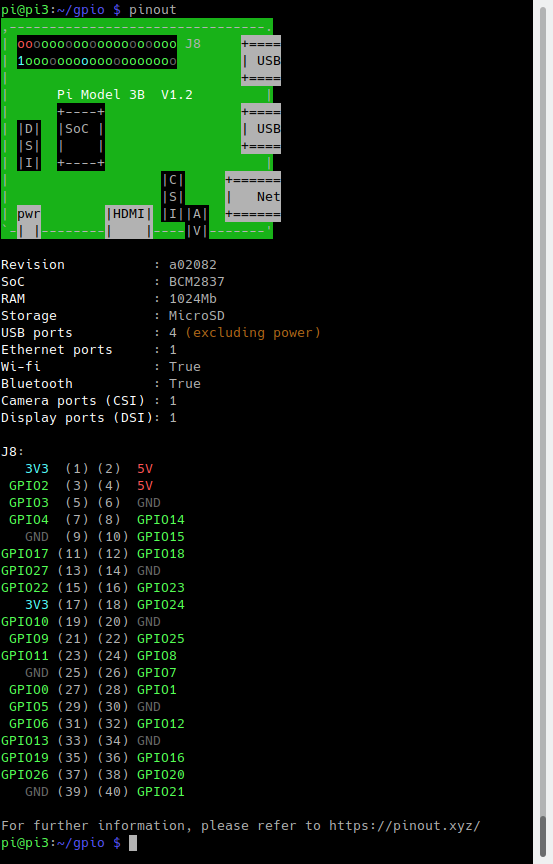
A handy command line tool called "pinout" is part of the library and will graphically show you the GPIO pins for the board it is running on (or any board revision that you specify):

The library is oriented around device and sensor types rather than inputs and outputs. For driving an output connected to an LED, for example, you use the LED module. You create an instance by passing the GPIO name. You can then call various methods like on() and off(). Here is a simple example that flashes and LED:
#!/usr/bin/python3
from gpiozero import LED
from time import sleep
led = LED(24)
while True:
led.on()
sleep(1)
led.off()
sleep(1)
The above loop could also be done by simply calling:
red.blink()
Which blinks an LED, defaulting to a rate of one second on and one second off.
Inputs pins are often connected to buttons, and in this case you can use the Gpiozero Button module, as in this example:
#!/usr/bin/python3
from gpiozero import Button
from time import sleep
button = Button(6)
while True:
if button.is_pressed:
print("Button is pressed")
else:
print("Button is not pressed")
sleep(1)
We can easily connect a switch so that when a pressed or released event occurs, we drive an LED high or low. This is event drived, so once set up, this works without any polling or further processing:
#!/usr/bin/python3
from gpiozero import LED, Button
from signal import pause
led = LED(24)
button = Button(6)
button.when_pressed = led.on
button.when_released = led.off
pause()
The call to pause() ensures that our Python program does not exit immediately, but rather keeps running until the user interrupts it with Control-C or similar.
Gpiozero has support for many devices - you can explore the documentation and try writing programs of your own. You can also extend it for new types of devices and sensors.
Conclusions
We've looked at a couple of popular modules for GPIO programming from Python. These are a great way to learn, especially for students and hobbyists. For commercial embedded applications you'll likely want to use a compiled programming language that is lighter weight and closer to the hardware so you can optimize performance and minimize resource usage. In Part 5 we'll look at how to program GPIO from C and C++. If you missed any installments in the series, you can find them here.