Experiment with this GPIO Learning Board
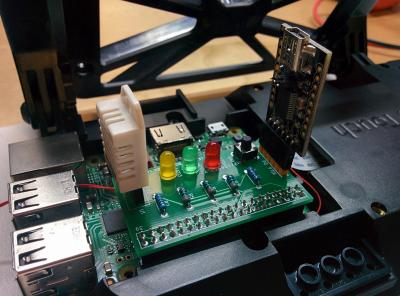
To facilitate hands-on labs for GPIO programming in our embedded training classes, ICS designed a small board that connects to a Raspberry Pi (or compatible) computer's GPIO connector and provides some simple functions for experimenting with GPIO programming.

The functions provided are:
- Red, green, and yellow LEDs, which can be individually turned on or off.
- A pushbutton whose status can be read.
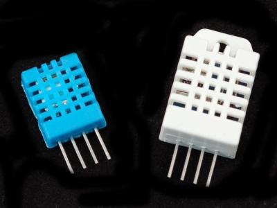
- A socket for a DHT11 or DHT22 temperature/humidity sensor.
- A connector for an FTDI USB-to-serial adaptor, which provides access to the serial port/console.
It is compatible with the the Raspberry Pi 2 or later (the Raspberry Pi version 1 has a smaller GPIO connector). It also works with the Raspberry Pi Zero if it has a GPIO header installed.

It is also compatible with the GPIO connector on a Toradex Colibri i.MX6 series SOM mounted on an Aster carrier board.

The tables below list the functions, GPIO connector pin numbers, and GPIO signal names for both types of boards:
Raspberry Pi 0/2/3/4:
| Function | P1 Pin | GPIO Name |
| Red LED | 18 | GPIO24 |
| Green LED | 22 | GPIO25 |
| Yellow LED | 29 | GPIO5 |
| Switch | 31 | GPIO6 |
| DHT | 37 | GPIO26 |
Toradex i.MX6 series Colibri SOM with Aster carrier board:
| Function | P1 Pin | GPIO Name |
| Red LED | 18 | GPIO52 |
| Green LED | 22 | GPIO53 |
| Yellow LED | 29 | GPIO63 |
| Switch | 31 | GPIO93 |
| DHT | 37 | GPIO51 |
The LEDs and switch are useful for basic GPIO programming of inputs and outputs.
The FTDI connector is useful for experimenting with serial port programming and allows this to be done with a desktop or laptop computer that doesn't have a built-in serial port. You can also use it to connect to the embedded board's serial console, which is useful in cases where the board is not available over the network.
A connector allows plugging in an inexpensive ($5 to $10) DHT11 or DHT22 temperature/humidity sensor. These sensors use a one-wire protocol that can be programmed using bit-banging techniques or using existing third-party code.

A fun little demo program I wrote takes the current temperature and relative humidity values, and applies a (surprisingly complicated) formula to calculate the heat index[2]. It then indicates the range or shade value using the LEDs as Safe (green), Caution (yellow), Extreme Caution (yellow flashing), Danger (red), or Extreme Danger (red flashing). It is under 100 lines of Python code.
These were the current values in my office as I was writing this:
Temperature: 23.0C/73.4F Humidity: 61.0%
Heat index: 24.7C/76.5F (Safe)
Outside it was:
Temperature: 33.0C/91.4F Humidity: 32.0%
Heat index: 32.3C/90.1F (Extreme Caution)
The board design is Open Source Hardware, licensed under the TAPR Open Hardware License. You are welcome to build the circuit and use the provided PCB layout. It uses all through-hole components and commonly available parts.
If you missed any installments in our GPIO programming series, you can find them here.