How to Use a Qt GUI App with Arduino and XBee for Wireless Communication
In this two-part series, we'll look at an interesting Internet of Things (IoT) application that uses an Arduino controller and two XBee wireless modules in conjunction with a Qt-based application.
Part 1 provides an overview, demonstrates communication between two applications using the XBee, and describes the hardware setup. Part 2 covers the configuration and programming of both the desktop application and the Arduino code.
Introduction
There are many different XBee models available with various wireless protocols, line of sight ranges, data transmission rates, RF frequencies, prices, and other characteristics. This blog reflects the XBee 802.15.4 module, sometimes known as an XBee Series 1 module. It has a range of up to 300 feet, data transmission rate of up to 250 Kbps, and is capable of point-to-multipoint network communication.
I'll show you how to use two XBees to build a point-to-point type network. Once you understand the basics presented here you can easily configure your network to point-to-multipoint, if you prefer. Specifically, I'll show you how to write the code that allows you to send and receive data via XBees to and from a desktop computer application written in C++ and Qt, as well as with an embedded application written for an Arduino board. (Thanks to Qt, this should run on a variety of desktop platforms with only small changes needed.)
A small LED circuit is also built with the Arduino, and the two applications together demonstrate sending a message from the desktop application to the Arduino that turns the LED on or off. You can also see data being sent from the Arduino to the desktop by looking at the Qt app's debug output. Both applications will ping each other and print a message when it has received the data from the other application.
XBee Overview
XBee is a product from Digi that communicates wirelessly with other XBee devices, which are compatible with both desktop and embedded devices. As mentioned earlier, there are many different models of XBees available. Some models use open standards such as ZigBee, 802.15.4, or Wi-Fi, while others use proprietary protocols developed by Digi, such as DigiMesh. (DigiMesh is based on ZigBee but reduces the complexity a bit.)
This variety of protocols allow for different types of network architectures to be built. An important distinction between models is the available line of sight ranges, which are much greater than Wi-Fi or Bluetooth. The ranges vary greatly between models: from 300 feet and 400 feet at the lower range, to 1 and 2 miles in the medium range, and up to 9 miles at the longer range.
There is also a 25-mile model available, though it may not be government certified to use in as many areas as other models. The data transmission rates vary a little between models. Most can transmit up to 250 Kbps, though a few transmit as low as 10 Kbps. The cost of the devices range from $17 to $45.
While the maximum line of sight range is much greater than Wi-Fi or Bluetooth, the data transmission rate is not nearly as fast. This essentially rules out using XBee for any video or audio streaming applications, though it can be useful in control or data-monitoring applications.
For instance, one product I worked on used XBees to transmit data to and from a quadcopter and a remote controller. The XBees were used to send commands to control the quadcopter, as well as to receive data from the quadcopter providing telemetry information about the vehicle.
Hardware Setup
I'll cover the following three setups in this blog:
- XBee-to-USB board that plugs into the desktop computer and is used by the desktop app
- Arduino and XBee shield that connects the XBee to the Arduino, which also connects to the computer to upload the app
- LED circuit that the example code uses as an example
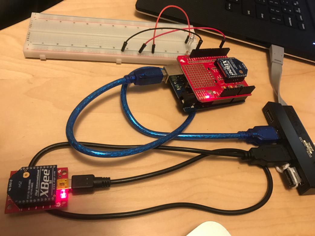
1 Desktop XBee Hardware Setup
You will need to choose a USB-to-serial base unit device that an XBee can connect to and that can be accessed as a serial device. This will allow compatibility with Qt's QSerialPort class, which I've used in the example. I chose to use this board. It allows you to connect an XBee. Then a cable with mini-USB to type-A USB connects the board to the USB port on a computer.
2 Arduino XBee Hardware Setup
First, you'll need an Arduino-compatible board that is compatible with the Arduino shield. (I used an Arduino Uno for the example presented in this blog.) If you aren't familiar with Arduino shields, they are boards that connect directly to the Arduino and add functionality to the system. Often, shields are stackable so you can easily add multiple shields to a single Arduino board. I chose to use this XBee shield.
The XBee will plug right into the shield. But connecting the shield to the Arduino requires soldering the headers to the shield, which then allows it to plug into the Arduino. If you're not sure how to solder the headers, find instructions at this site, or if you have a different shield refer to the instructions that came with it.
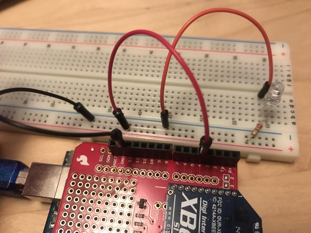
3 Arduino and LED Circuit
The Arduino application included the downloadable example code turns the power on at pin 4 when the user presses the 'Turn On' button in the desktop application. If you have a circuit connected, it will come to life when the power turns on. A simple circuit you can use has a resistor connected to pin 4, followed by an LED, which is then connected to ground back on the Arduino shield. The downloadable code will use this circuit and the desktop application will control the LED.
Summary
In part two, we'll cover the configuration and programming of both the Qt-based desktop application and the Arduino code. Stay tuned.