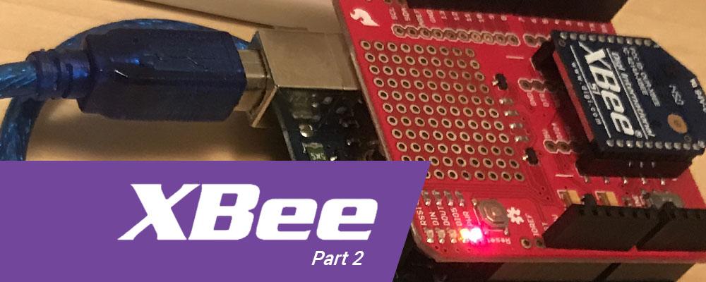
How to Use a Qt GUI App with Arduino and XBee for Wireless Communication (Part 2)
In part one of this blog series, I gave an overview and described the hardware setup for an IoT example application that uses a Qt-based desktop program and an Arduino with XBee wireless modules. In part two, we'll cover the software configuration and programming.
Configuring and Programming the XBee Module
The XBees need to be programmed and configured so that they can communicate with each other. Both applications interact with the XBee as a serial port device. Our Qt application will use Qt's QSerialPort class to interact with the XBee and the Arduino will use Arduino's built-in SoftwareSerial class to control the XBee.
To get the XBee set up in the Qt application, the high-level steps involved are:
- Search available serial ports and select the port with the desired XBee device.
- Create the QSerialPort object and open it for reading and writing.
- Configure the serial port properties.
- Configure the XBee properties.
Step 1 - Search available serial ports and select the port with the desired XBee device
In a Qt application the static function QSerialPortInfo::availablePorts() will return a list of QSerialPortInfo objects that tells us information about available serial ports such as port name, manufacturer, serial number, and other information. Some of these properties may be empty and will depend on the device you're using.
You can decide which is the best way to find your device using the available information given in the QSerialPortInfo object. The downloadable source code uses the serial number to select the device, and also confirms that the port name is correct for the platform. (It will be different for each platform.) If running the example code, make sure to change the serial number that is hardcoded in the m_deviceSerialNumber property in serialportdesktop.h. If you don't know the serial number of the device, run the application and look at the debug output. It will print out the serial number, among other information, for each serial device it finds.
Step 2 - Create the QSerialPort object and open it for reading and writing
When you create the QSerialPort object, pass to the constructor the port name as it is found in the QSerialPortInfo object, then call the object's QSerialPort::open(QIODevice::ReadWrite) function to open it as a readable and writable device.
Step 3 - Configure the serial port properties
Qt needs to configure the following serial port attributes. QSerialPort has convenience functions to set each one of these:
- Baud rate: 9600
- Data Bits: 8 Bits
- Parity: No Parity
- Stop Bits: One Stop Bit
- Flow Control: No Flow Control
The relevant code is pretty straightforward:
serialPort->setBaudRate(QSerialPort::Baud9600);
serialPort->setDataBits(QSerialPort::Data8);
serialPort->setParity(QSerialPort::NoParity);
serialPort->setStopBits(QSerialPort::OneStop);
serialPort->setFlowControl(QSerialPort::NoFlowControl);
Step 4 - Configure the XBee properties
The XBee needs two properties configured: the network ID and the channel of the XBee device. These must be configured to the same value on both XBees in order for them to communicate with each other.
XBees operate on the 2.4 frequency band, and the channel ID sets where within that band it operates. Valid values are 11 through 26 (though 11 and 24-26 are only available on newer XBees). 11 is the frequency 2.405GHz, 12 is 2.410GHz, 13 is 2.415GHz, and it continues to increment by .005 all the way to 26 (26 being 2.480GHz).
In addition, the 'destination address' and 'MY address' can be configured to create more complex networks by setting the address of the target device to receive the messages — but we will leave them as the default values since we are only sending data between two XBees.
To configure an XBee you must put it in 'Command Mode' before sending commands. Once in command mode it will acknowledge and, if necessary, respond to commands. Command mode will exit automatically after a set amount of time (by default 10 seconds) or when the exit command mode command is sent. Each command will return "OK\r" if it is successful. Enter command mode by sending the string "+++", when the "OK\r" string is returned then you can begin sending other commands. The command to exit command mode is "ATCN\r".
To configure the network id and channel, our application needs to perform the following commands:
- Send command "+++" to enter command mode, wait for "OK\r" string
- Send command "ATCH18\r" to set the channel to 18 to operate at 2.440GHz, then wait for "OK\r" string
- Send command "ATID68\r" to set the network ID to 68, then wait for "OK\r" string
- Send command "ATCN\r" to exit command mode, then wait for "OK\r" string
The XBee device should now be ready to send and receive data. In Qt 5.7, QSerialPort has several ways to read data. Normally, I would connect to QSerialPort's readyRead() signal to catch when data is available, but in this use case I found that this signal is not always emitted even when there is data ready to be read.
To work around this I set up a timer to intermittently call QSerialPort's waitForReadyRead() with a small wait time and then used QSerialPort's read(char* buffer, int maxLength) function, which returns the amount of data read into the buffer and can be used to determine if any data was read and set to the buffer passed in as the first argument. QSerialPort::write(char* data, int maxLength) can be used to send data.
To configure and program XBee with Arduino, the high-level steps are:
- Create SoftwareSerial object and initialize it for reading and writing.
- Configure the XBee properties.
- Explore other useful XBee commands.
Step 1 - Create SoftwareSerial object and initialize it for reading and writing
Creating a SoftwareSerial object with 2 arguments passed to the constructor, 2 as the first argument and 3 as the second argument indicates Arduino pin 2 will be the RX pin and pin 3 will be the TX pin. After this, the object function call begin(9600) will initialize the serial port and make it ready to read and write to, the 9600 argument sets the baud rate to 9600 bps. The SoftwareSerial class sets the serial port's other properties to the same as we set in the C++/Qt application (SERIAL_8N1, or 8 data bits, no parity, one stop bit).
Step 2 - Configure the XBee properties
Just like with the C++/Qt application, we need to put the XBee in command mode and set the channel and network ID to 18 and 68 respectively. Notice these values are the same values set to the other XBee. The matching values are required for two XBees to communicate with each other. We can use the SoftwareSerial object's write() function to send commands, and the available() function to see if data is available to read, and read() to read new incoming data.
Just like for the C++/Qt application, the steps to configure the XBee are:
- Send command "+++" to enter command mode, wait for "OK\r" string
- Send command "ATCH18\r" to set the channel to 18 to operate at 2.440 GHz, then wait for "OK\r" string
- Send command "ATID68\r" to set the network ID to 68, then wait for "OK\r" string
- Send command "ATCN\r" to exit command mode, then wait for "OK\r" string
The XBee should now be ready to send and receive data using SoftwareSerial's reading and writing functions. You can find a reference and full function list for SoftwareSerial here.
Step 3 - Explore other useful XBee commands
Two other commands you may find useful are "ATRE\r" and "ATWR\r". "ATRE\r" resets the XBee to default settings. "ATWR\r" saves the current configuration to non-volatile storage, respectively. Expect an "OK\r" response for both of these commands, as well. A larger list of XBee commands, along with other XBee info, is available here.
Running the Example
When running the example code, look for a switch on the Arduino/XBee shield with options for DLINE or UART and make sure it is on DLINE. Deploy and run the Arduino application first and open the debug output window. When you see a message telling you the XBee is configured successfully, run the C++/Qt application. Look at the GUI window or the debug output for the C++ application. When you see a message indicating the XBee configuration is successful, you can then hit the 'Turn On' or 'Turn Off' buttons to send messages over the XBee devices to control the LED on the Arduino.
Now, when the Arduino application receives the 'Turn On' message from the XBee (simply a 'T' char), pin 4 will output power and the LED will turn on. When the Arduino application receives the 'Turn Off' message from the XBee (a 'F' char) the application will turn power off to that pin and the LED will shut off.
You'll also see that the desktop application intermittently sends a ping to the Arduino (a 'P' char) and when the Arduino receives this it will respond with a ping back to the Desktop XBee (also a 'P').
Conclusion
I hope this blog has helped you understand XBees enough that you can integrate them into your own applications, whether you have two desktops chatting with each other, or a Raspberry Pi application controlling an Arduino robot.
References
- XBee Buying Guide, Digi web site, http://docs.digi.com/display/XBeeArduinoCodingPlatform/XBee+buying+guide
- XBee Buying Guide, SparkFun web site, https://www.sparkfun.com/pages/xbee_guide
- Digit XBee web site, https://www.digi.com/lp/xbee
- USB/XBee Base Unit, SparkFun, https://www.sparkfun.com/products/11812?_ga=1.70539353.871985025.147688…
- Arduino/XBee Shield, SparkFun, https://www.sparkfun.com/products/12847
- Arduino Shield Hookup, Installing Headers, https://learn.sparkfun.com/tutorials/arduino-shields/installing-headers…
- Arduino Shield Hookup Guide https://learn.sparkfun.com/tutorials/xbee-shield-hookup-guide
- XBee Configuration, - Configuring Networks, https://learn.sparkfun.com/tutorials/exploring-xbees-and-xctu/configuri…
- XBee Configuration - Arduino Wireless Shield, https://www.arduino.cc/en/Main/ArduinoWirelessShield
- XBee Configuration - Ardino XBee Shield. https://www.arduino.cc/en/Main/ArduinoXbeeShield
- Arduino Wireless Shield Guide, https://www.arduino.cc/en/Guide/ArduinoWirelessShield
- XBee Channel Map, http://www.digi.com/wiki/developer/index.php/Channels,_Zigbee
- Qt QSerialPort Reference, http://doc.qt.io/qt-5/qserialport.html
- Arduino SoftwareSerial Reference, https://www.arduino.cc/en/Reference/SoftwareSerial
- General Arduino Reference, https://www.arduino.cc/en/Reference/HomePage
- Downloadable source code for example application, ftp://ftp.ics.com/pub/pickup/xbee_example_arduino_qt.zip